

『Frc Flow Meter Displays: Calibrating Fire Research Corp Digital Flowminder GPM Panels for Firetrucks』Related information(clamp on meter|electromagnetic meter|venturi meterrotameter|orifice meter|ultrasonic flow meter|mass flow meter|coriolis mass flow meter|coriolis flow meter|magnetic flow meter|magmeter flow meter|magflow flow meter|mag meter flow meter|electromagnetic flow meter|vortex flow meter|turbine flow meter|thermal mass flow meter|thermal flow meter|rotameter flow meter)
FRC Flow Meter Displays: Calibrating Fire Research Corp Digital Flowminder GPM Panels for Firetrucks
Quick Answer: A Digital Flowminder panel shows fire truck discharge flow in gallons per minute. Calibration needs a known flow reference, the correct K-factor, and a zero flow adjustment. Silver Instruments supplies compatible flow sensors and display panels for fire pump test benches and fire apparatus service centers.
What the Digital Flowminder GPM Panel Does on a Fire Truck
Fire pump operators use a digital GPM display during discharge operations. The FRC Flowminder panel receives a frequency signal from a flow sensor mounted in the discharge pipe. The panel converts that frequency into a flow rate in gallons per minute. A typical turbine flow sensor sends 1000 pulses per gallon or another fixed pulse rate. The display uses a K-factor to convert pulses to GPM. That number sits in the panel memory.
Fire departments in Southeast Asia and Latin America often run pump tests after hose replacement or nozzle changes. A wrong K-factor leads to a flow error of 5 to 15 percent. On a 1500 GPM pump, a 10 percent error means 150 GPM of false flow reading. That affects discharge pressure decisions and water supply calculations.
Calibration Steps for Fire Research Corp Digital Flowminder Panels
Most engineers skip this part but it matters on every pump panel. Calibration starts with the sensor installed in a straight pipe section. You need 10 pipe diameters upstream and 5 downstream if you can. For a 2 inch discharge line that means 20 inches of straight run before the flow sensor. Use a clamp on or inline flow reference meter. A reference meter with an accuracy of plus or minus 0.5 percent works best.
Step 1. Zero the display. Close the discharge valve and stop all water flow. Go to the calibration menu on the Flowminder panel. Select zero flow. Wait 15 seconds. The display should read 0.0 GPM. If it drifts by plus or minus 1 GPM, check for air in the line. Air bubbles cause unstable pulses.
Step 2. Enter the K-factor from the flow sensor tag. Fire Research Corp sensors often have a K-factor like 10.25 or 21.50 pulses per gallon. Check the sensor data sheet. Do not copy a K-factor from a different pipe size. A 2.5 inch sensor has a different K-factor than a 3 inch sensor.
Step 3. Run a known flow. Use a calibrated flow bench or a master flow meter. Set the pump to 250 GPM. Read the reference meter and the Flowminder display at the same time. Allow flow to settle for 20 seconds. The difference between the two readings is your error.
Step 4. Adjust the calibration factor. The FRC panel may let you enter a correction multiplier. For example if the panel reads 260 GPM against a 250 GPM reference, the multiplier is 250 divided by 260 or 0.9615. Enter that value and retest. Repeat at 500 GPM and 1000 GPM if the pump has multiple discharge stages.
Common Calibration Problems on Fire Truck GPM Panels
Here is the thing. We have seen this on customer sites many times. The number one problem is incorrect wiring from the flow sensor to the display. A frequency signal can be picked up by the panel as a clean square wave. If you run sensor cable next to the engine alternator cable, electrical noise adds extra pulses. The display then shows a flow rate that jumps around.
The second problem is sensor installation depth. Insertion flow sensors must sit at the correct depth in the pipe. If the sensor tip is too high in a horizontal pipe, it reads low flow. If the tip is too low,
The third common problem is using water with high conductivity or particles. In some mining or construction fire trucks, water comes from ponds or rivers. Sand and silt wear the rotor bearings. A damaged rotor still sends pulses but the K-factor changes. Check the rotor for free spin every 6 months.
Replacement Flow Sensors and Compatible GPM Displays
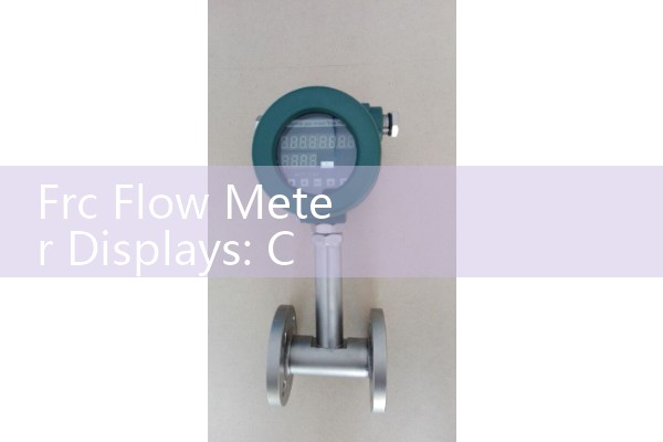
Fire Research Corp Flowminder panels are reliable but sensors do fail. You do not always need to replace the display. A compatible turbine flow sensor with a 5 V square wave output can work with most FRC panels. The key parameters are pulse output, frequency range, and K-factor range. A sensor rated for 3 to 100 GPM works for small booster lines. A sensor rated for 50 to 1500 GPM suits main discharge lines.
Some newer fire pump controllers accept 4-20 mA HART instead of pulse signals. Silver Automation Instruments can supply electromagnetic flow meters with 4-20 mA HART output for those systems. These meters provide stable readings in dirty water with suspended solids.
Silver Automation Instruments supplies industrial flow meters for fire pump test loops, foam proportioning systems, and water transfer skids. We stock turbine flow meters, electromagnetic flow meters, and oval gear flow meters. If your fire truck uses foam concentrate, an oval gear meter measures low flow rates down to 0.5 GPM. A turbine meter works better for main water flow up to 2000 GPM.
A fire truck service center in Vietnam replaced nine FRC flow sensors last year after bearing wear. They used Silver Instruments turbine sensors with the same pulse output and K-factor range. The panels passed a 1000 GPM pump test after calibration.
Send us your pressure in bar, temperature in Celsius, pipe size in DN, and flow range in GPM or liters per minute. We can recommend a direct replacement flow sensor or a complete GPM display panel for your fire apparatus. Contact Silver Instruments at Tel: +86-135-1213-1526, WhatsApp: 86-135-12131526, WeChat: +86 13512131526. See flow-meter.com.au for industrial flow meter specifications.
FAQ: Fire Research Corp Digital Flowminder Calibration
How often should I calibrate a Flowminder panel on a fire truck?
Answer: Calibrate once per year or after any flow sensor replacement. Fire departments that pump dirty water should calibrate every 6 months. Annual pump tests per NFPA 1911 include flow accuracy checks.
What K-factor should I enter for a Fire Research Corp flow sensor?
Answer: Use the K-factor printed on the sensor tag. A typical FRC insertion sensor uses 10.0 to 21.0 pulses per gallon. Do not use the K-factor from memory.
Can I calibrate without a flow bench?
Answer: Yes but with less accuracy. Use a master flow meter with known calibration. Or collect water in a calibrated tank and measure volume over time. A 500 gallon tank and a stopwatch can give reference flow within 2 percent.
Does Silver Instruments sell a replacement display for Fire Research Corp panels?
Answer: We supply compatible industrial displays and flow sensors. We can match the signal type and panel cutout size. Send us the existing panel model number and sensor K-factor.
Why does my Flowminder read negative or zero at idle?
Answer: Check the sensor wiring polarity and zero calibration. A loose ground or reversed signal wire sends inverted pulses. Re-zero the panel after all air is removed from the pump volute.
 Hot Blog
 Related AD